The plans were drawn up in my tiny mind as to how I could operate an Enforcement Droid 209 so now I had to write them down, test ideas and start building. It was September 2016 with the Comic Con set to be the weekend of 19th and 20th November the same year. Just over two months to crack this challenge.
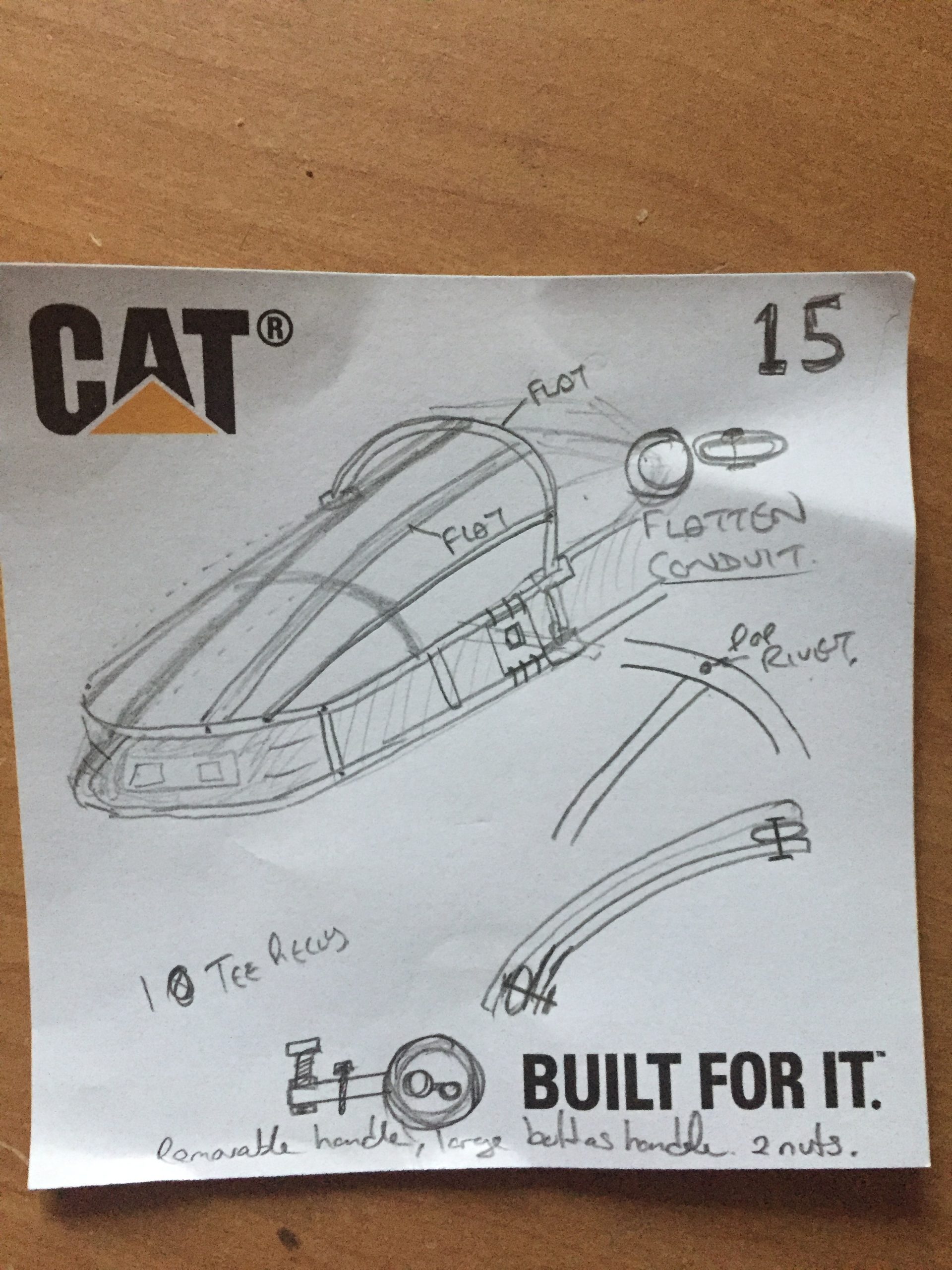
I’m not a graphic designer or a user of any CAD packages or anything like that so I chose to make notes on Post It size notes from my block of notelets. It happens to be a Caterpillar notelet block but this project was in no way endorsed by them.
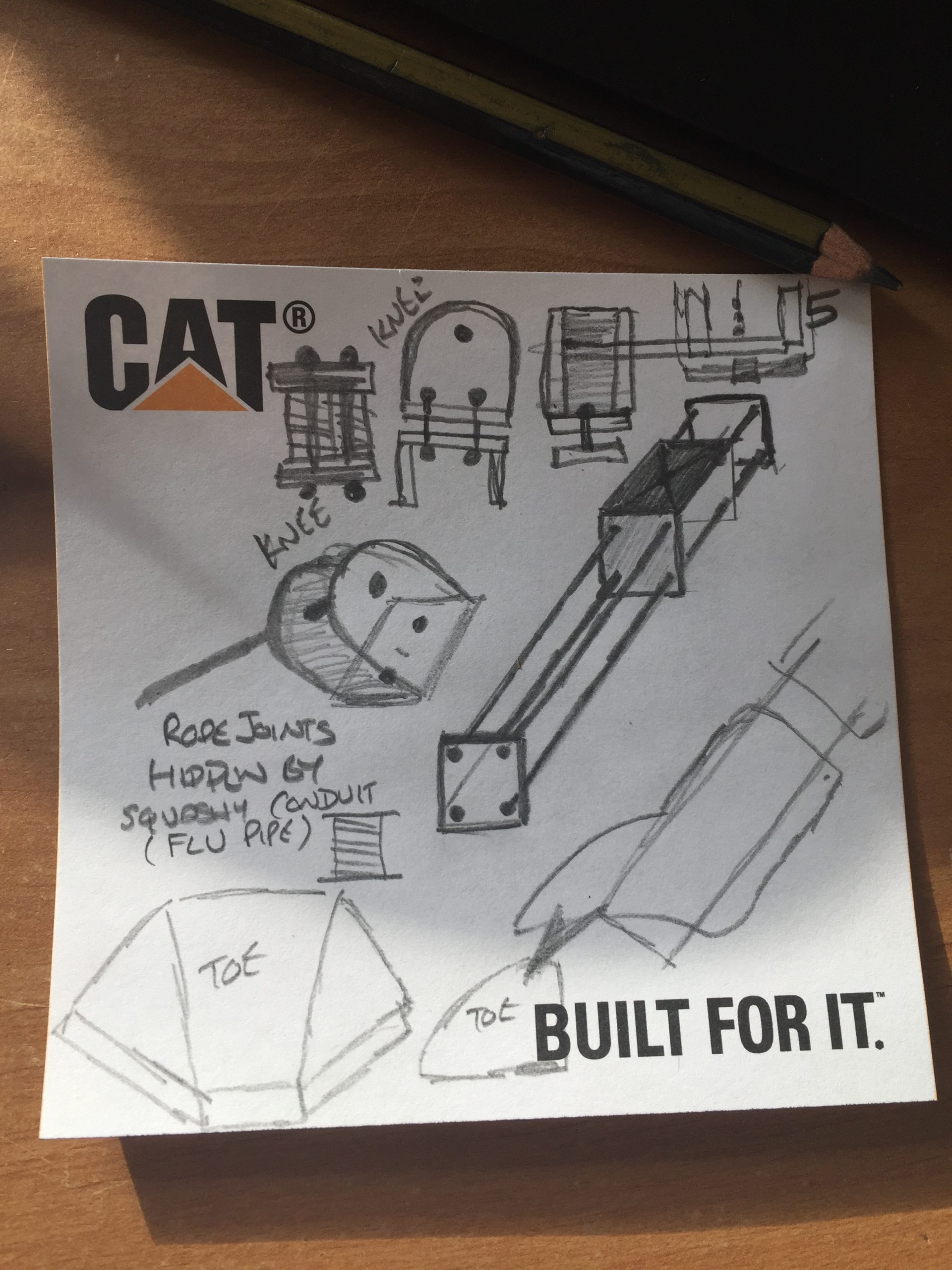
As you can see from the initial set of notes I was interested in production of the legs of the droid. I worked out that my ED-209 legs would not articulate the same and the knee joint would be hinged but would not go up and down the leg as it does in the movie. I contemplated the material I could use to make a pair of legs strong enough to be operated by my walking action but light enough to not be a huge burden on me when I was wearing them.
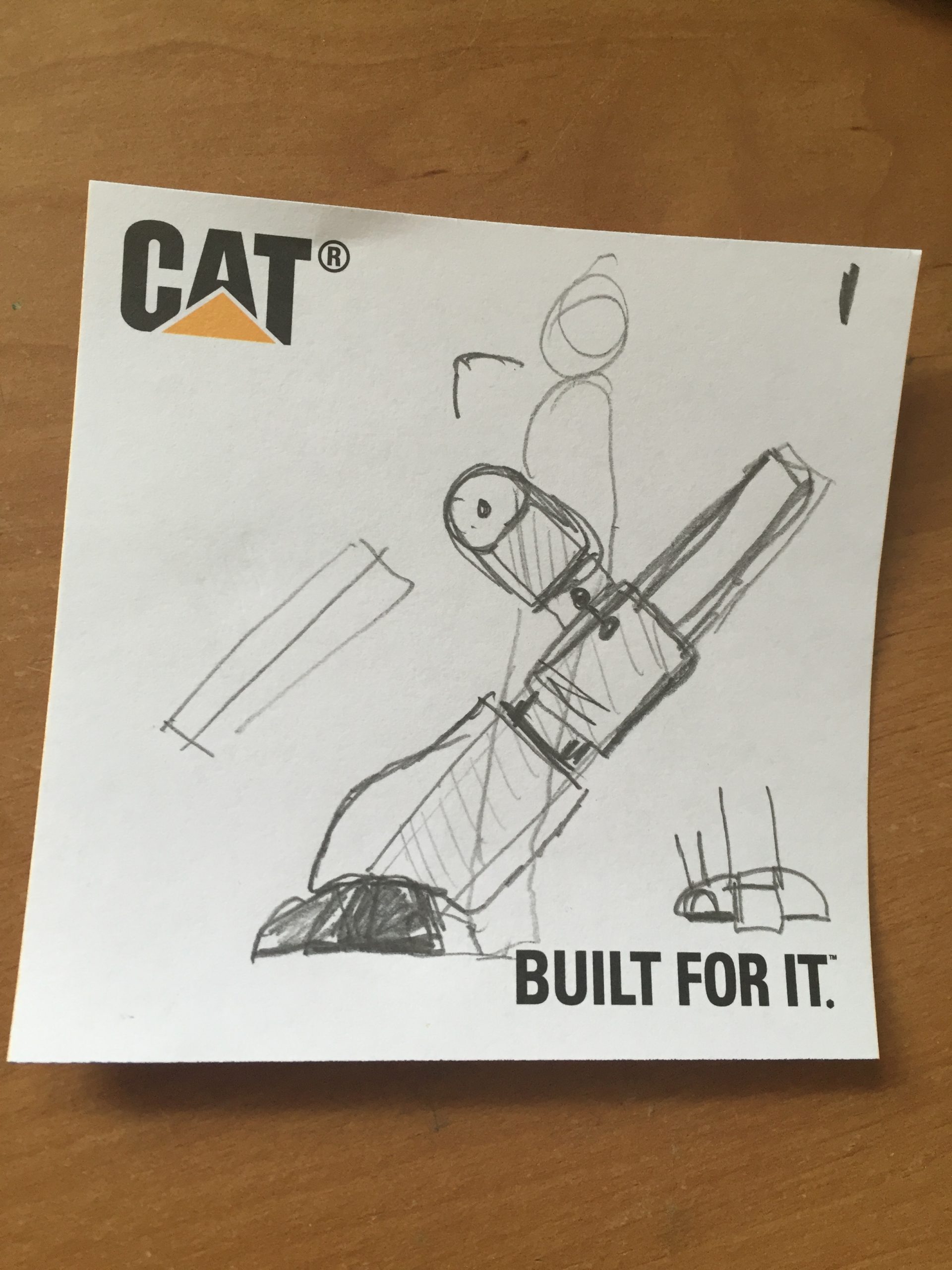
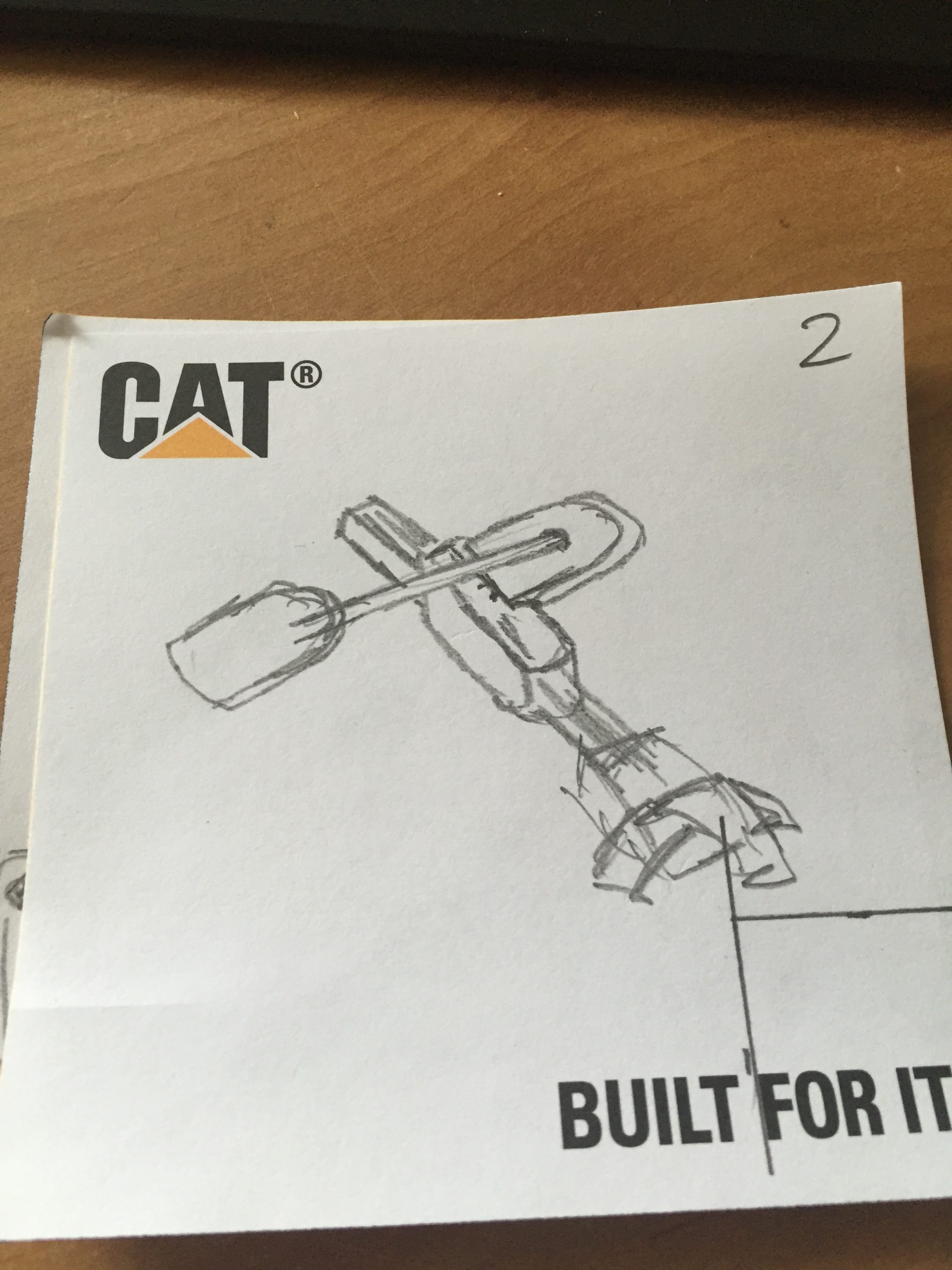
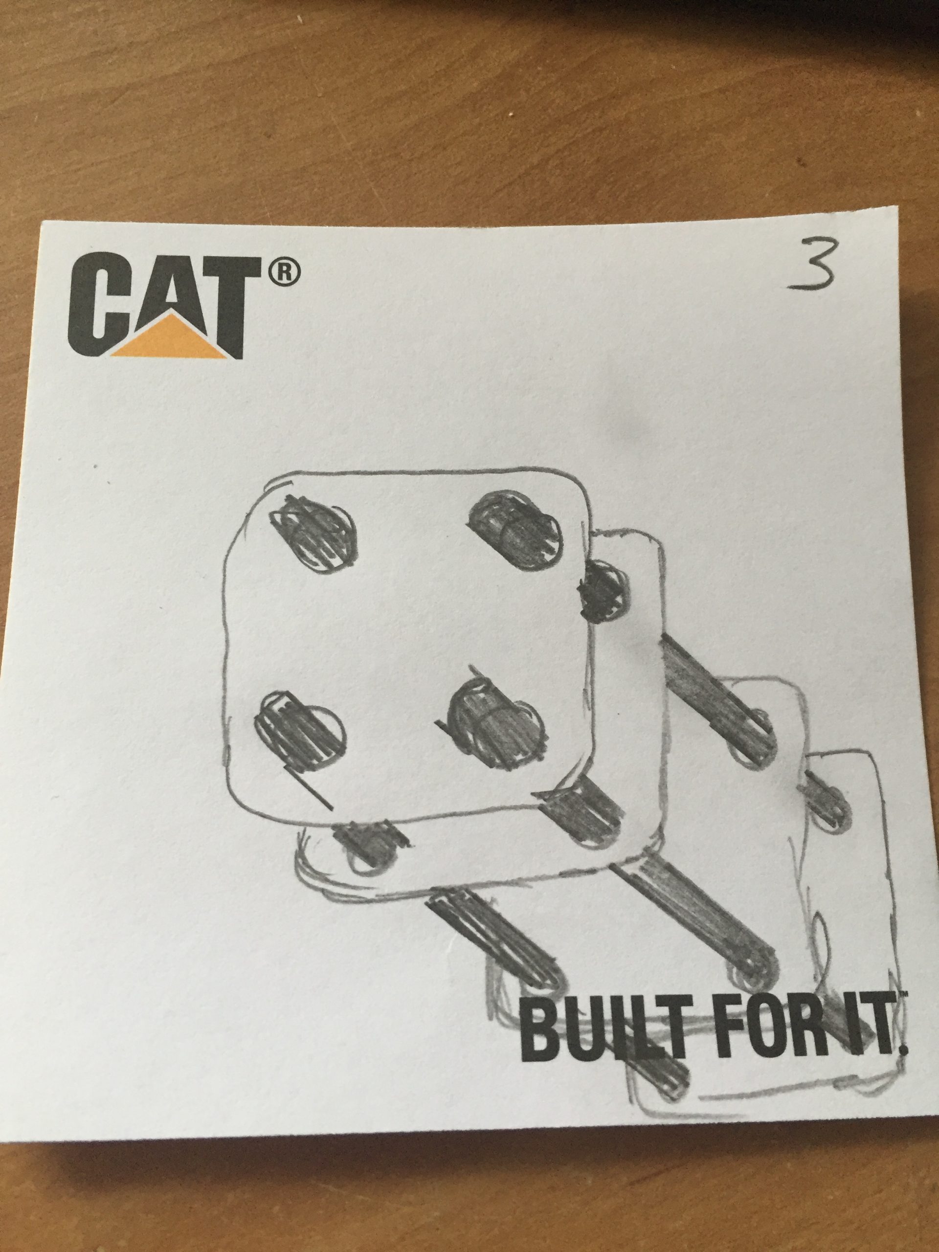
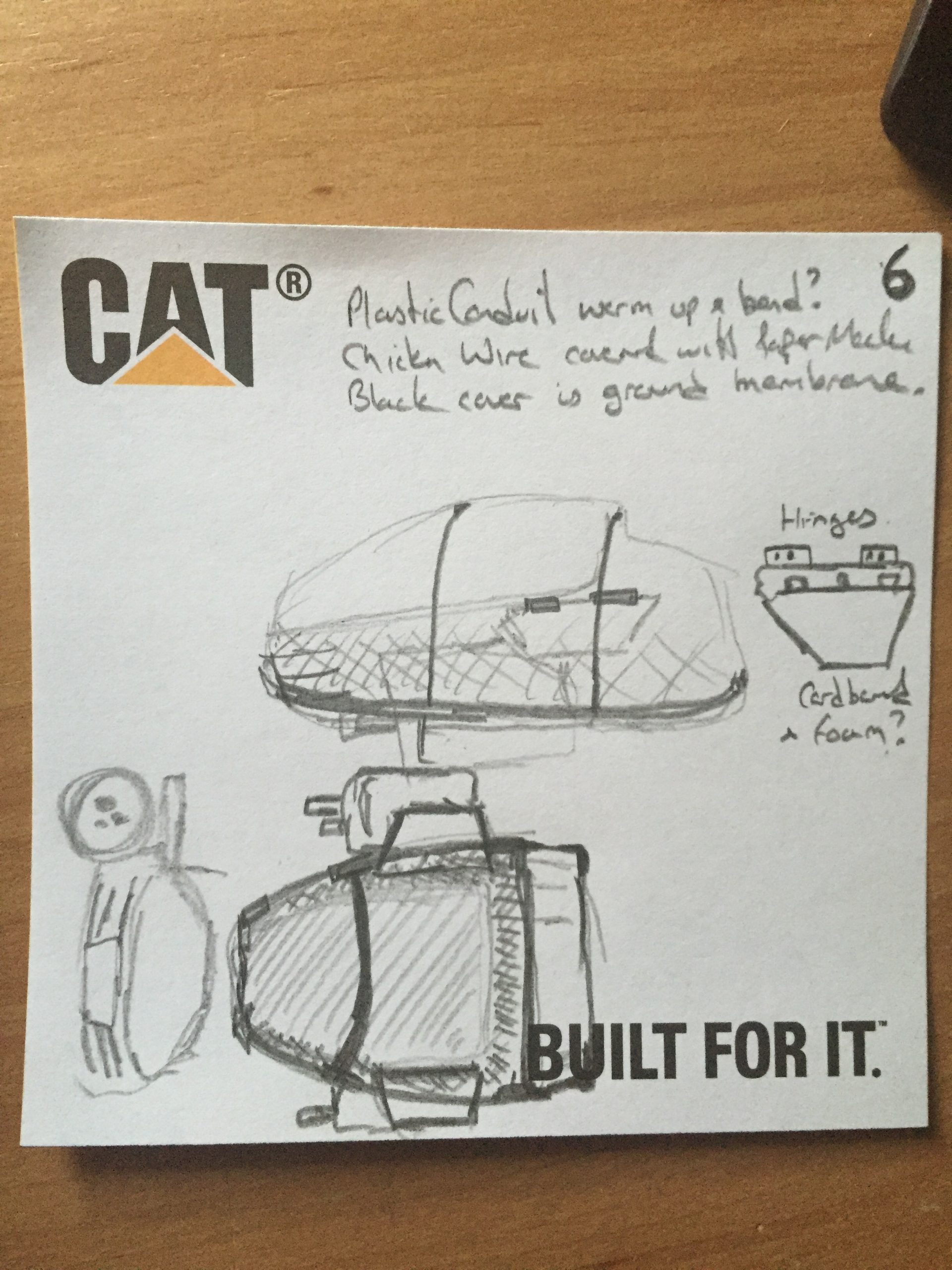
Notes 1-10 mainly concentrated on the legs and feet but a couple of them, 6 and 9 focussed on the remainder of the outfit, ie. the body and guns. In note 6 you can see the idea of using plastic conduit to produce the shape of the body and we’ll see more of this later. In note 9 you can see there is some thought given to the movement of the gun pods from the inside of the costume. Some linkages were considered after seeing a superb you tube video for a remake of the scene in which ED-209 is introduced to the board, detailing a more screen realistic model and the method of moving the gun pods on that. We’ll come back to this later too.
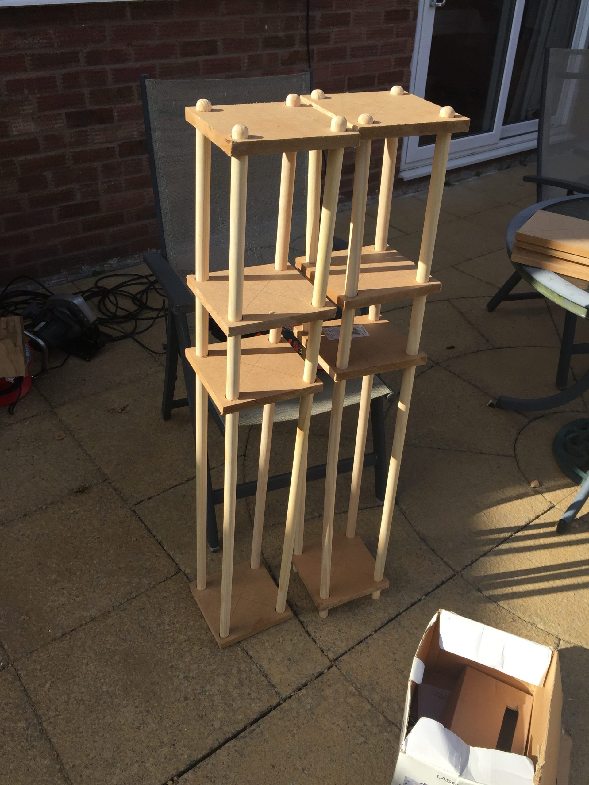
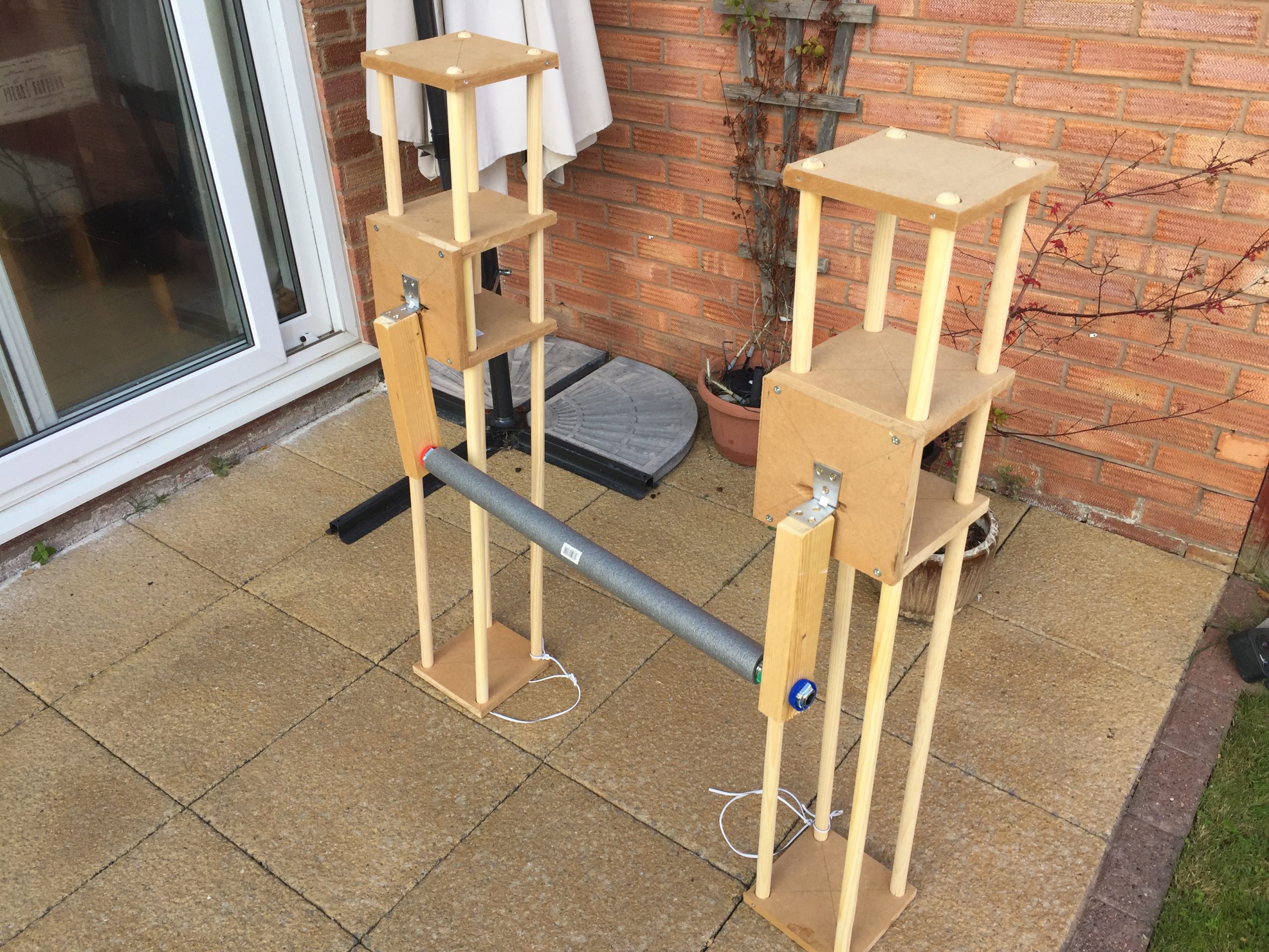
The first part I bought were the eight broom sticks which were cheaper than special dowels or planed rectangular wood. These were sourced from Boys & Boden in Shrewsbury. Using some old MDF from the shed I chose a size to make the legs and cut four squares of MDF to join the broom handles together and form a leg. You can see in the following pics how these developed. Once all slotted together I placed some small screws through the side of the MDF and secured these to the broom sticks. A couple of the MDF parts split but it was tight enough that I wasn’t too worried.
The height of the centre two pieces was to be decided on once I’d tested the reverse facing knee and the joint for the hip. Hopefully this would indicate where this section needed to be. Also I wanted to have enough of the open part at the top to make it look like there was travel left.
You can see back in note 5 that I contemplated using a rope knee joint between the lower leg and upper leg but I soon figured out that I’d be better using a metal hinge for more rigidity. Note 10 shows how I planned to use fizzy drinks bottles as the pistons above the knee too, this didn’t happen as you’ll see later on.
Body Work
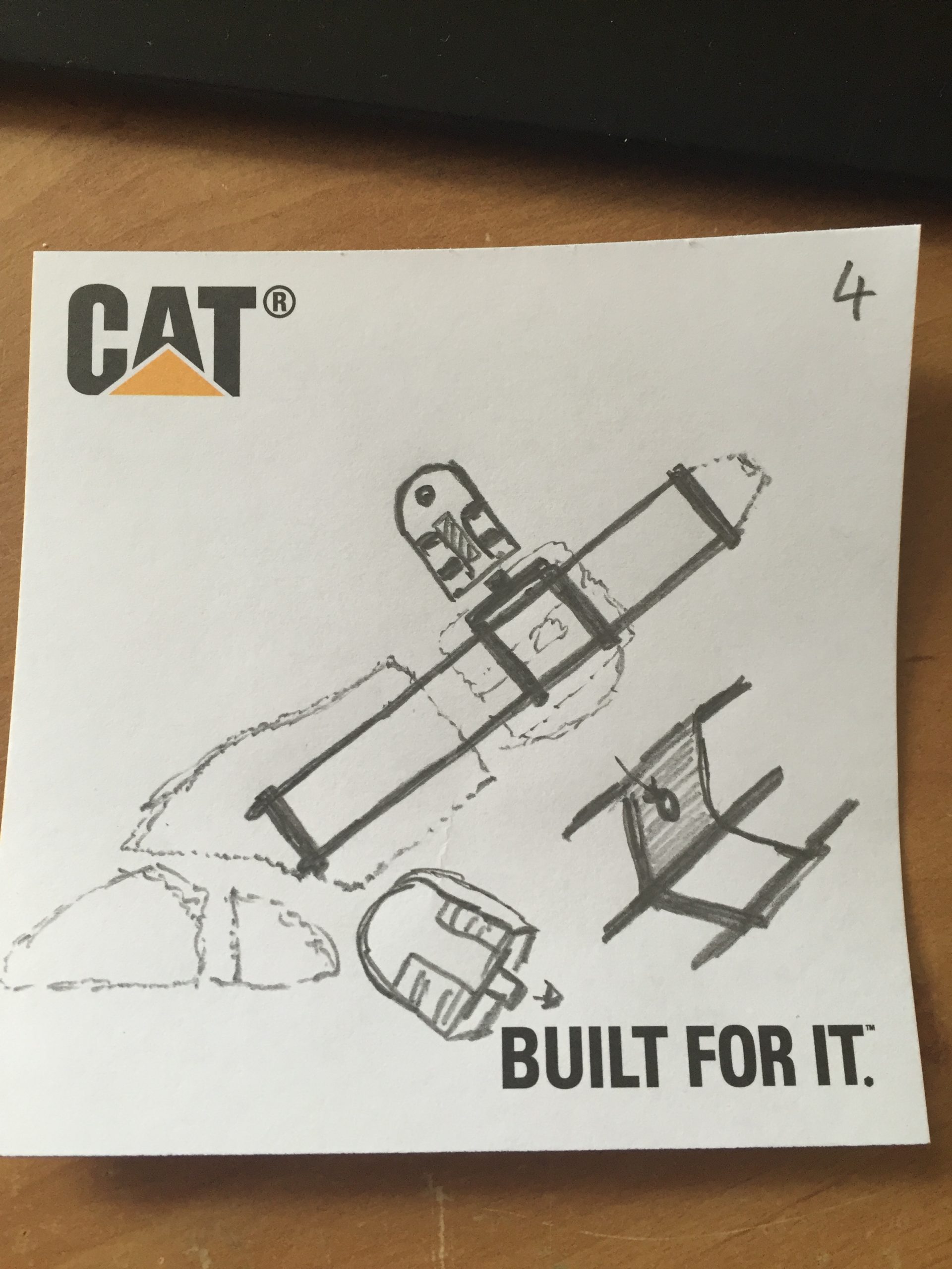
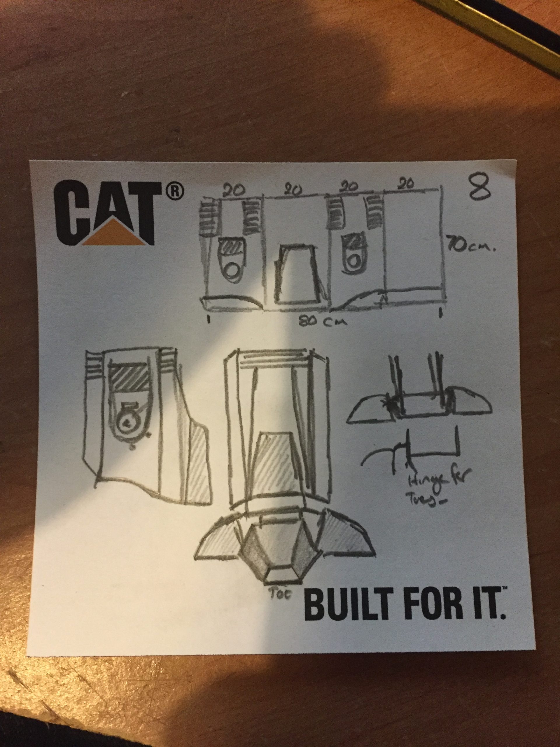
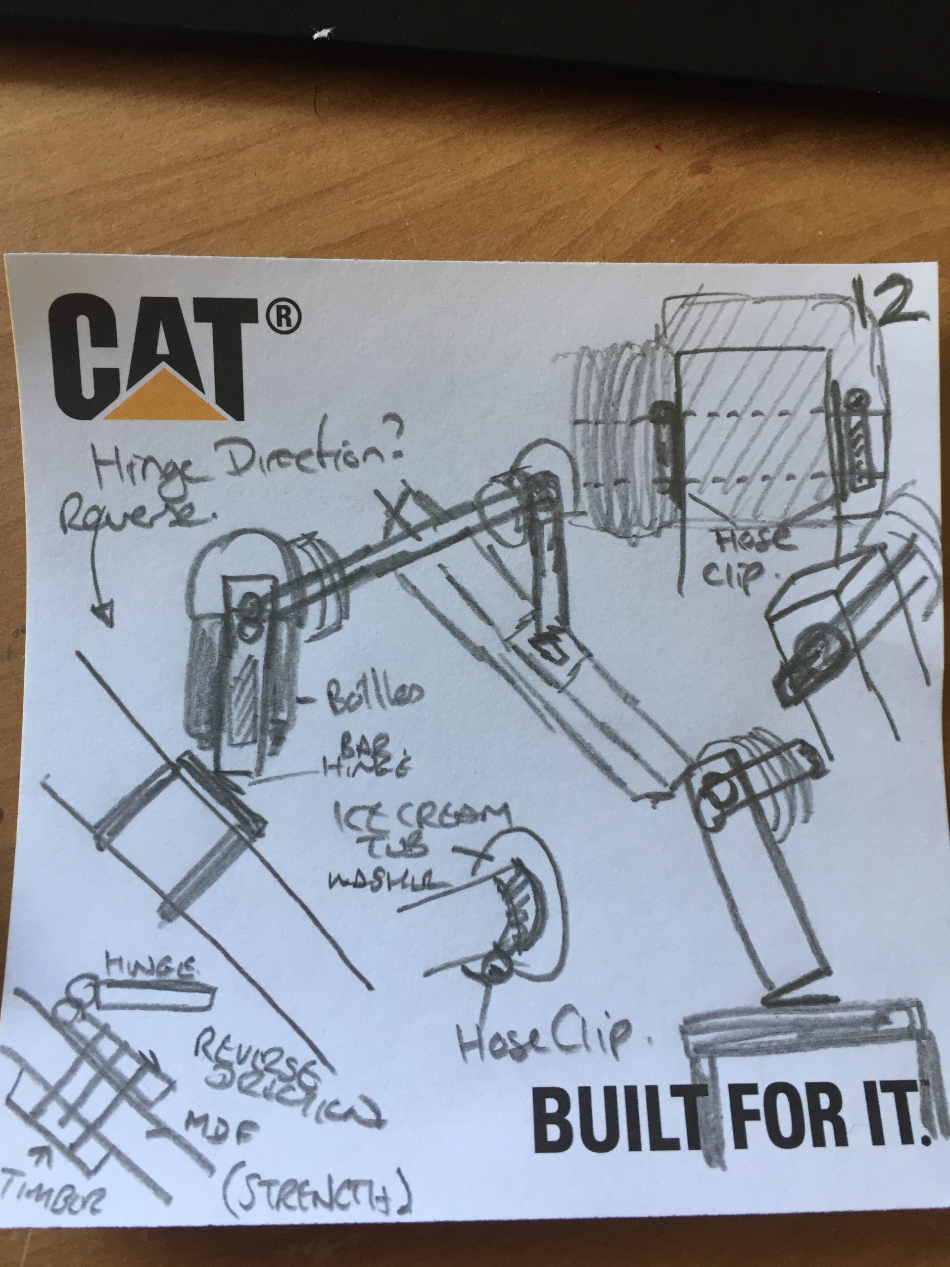
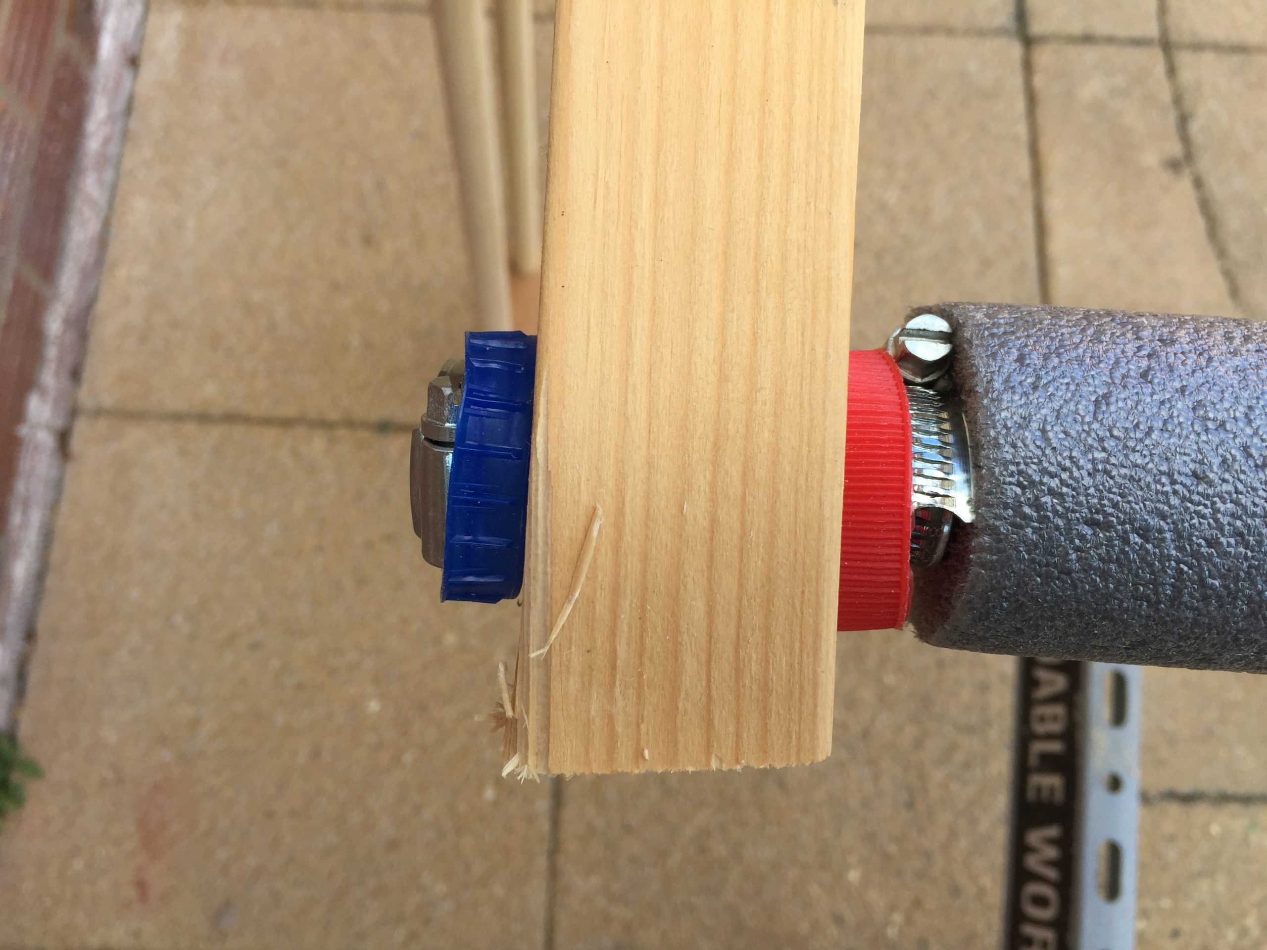
Note 11 shows a simple plan for the body of the robot using 20mm plastic electrical conduit, I’d come back to flesh this out more and carried on thinking about the knee. I was concerned about the joint of the knee and didn’t know whether to have the hing opening one way or the other. Making little models out of pencils and rubber bands led me to believe that the hing would be better if the hinge were closed at normal standing position and open when the foot was lifted. It seemed to give the leg movement more of an articulated look. On Note 12 you can see that I’d thought about how I was going to join the legs at the hips. A single metal pipe through the wooden upper leg and then held on with pipe clips. These would be separated from the wood by washers made from milk bottle tops.
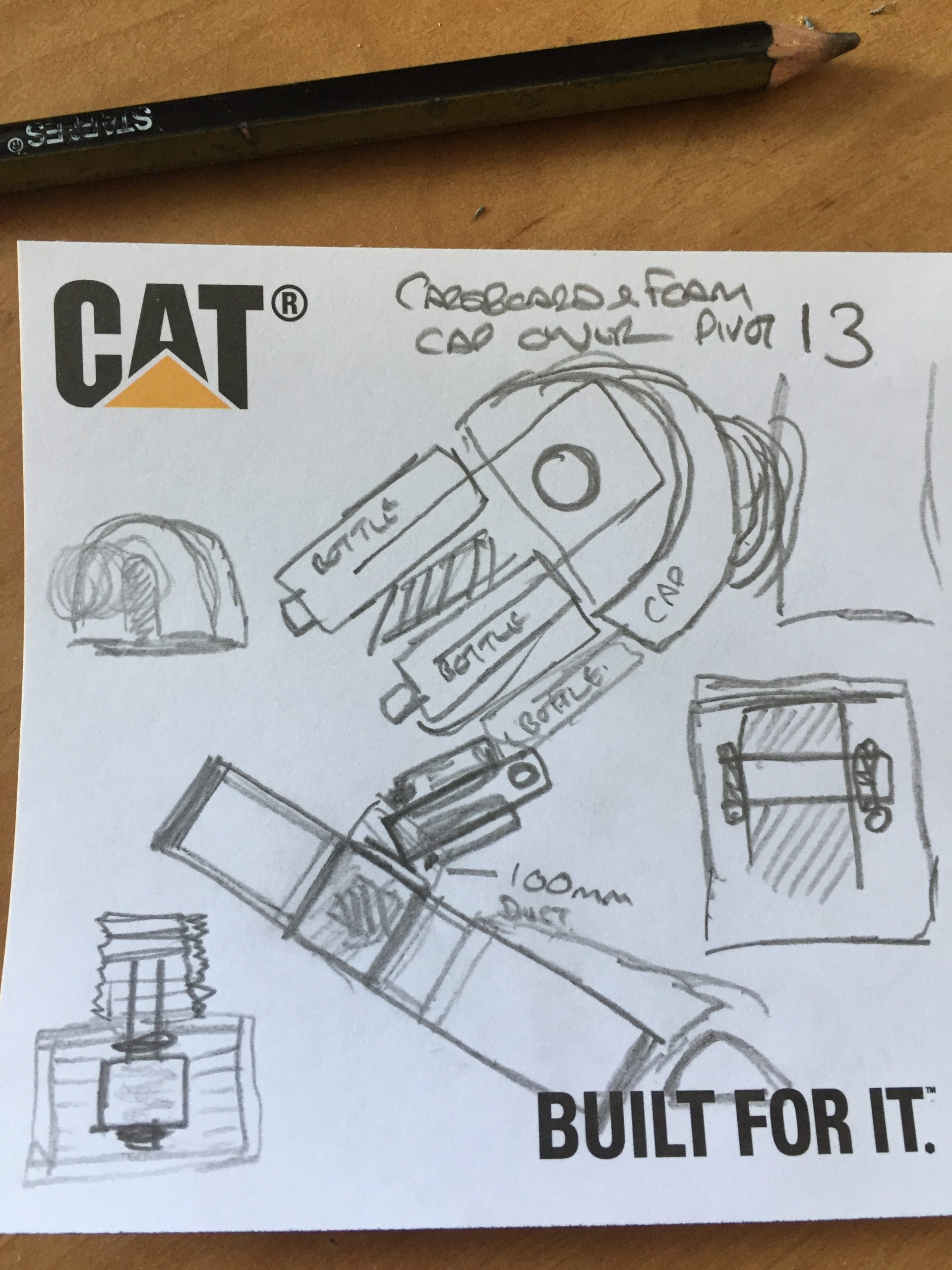
Note 13 shows the final hinge layout and more design for the cover of the hip joint. Ideally I’d like it to be the same as in the film but I was to end up making changes that would alter it’s appearance. No biggy though!
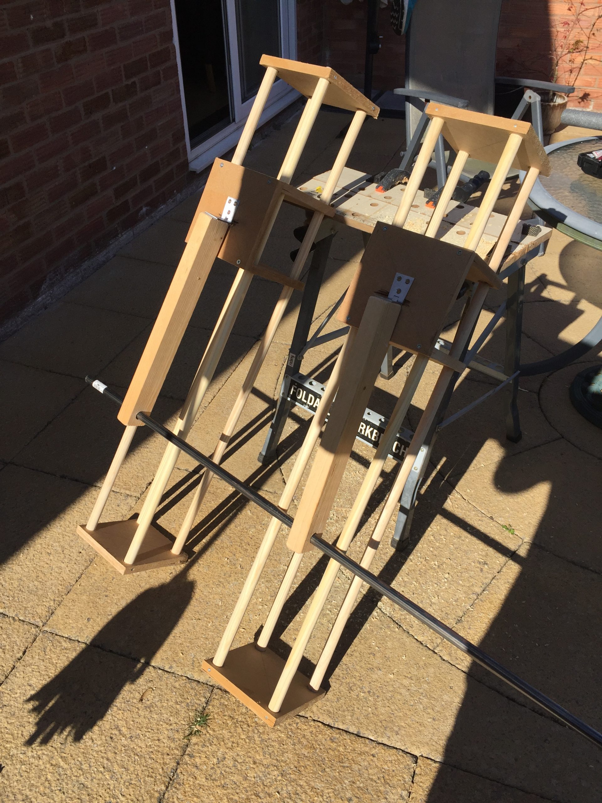
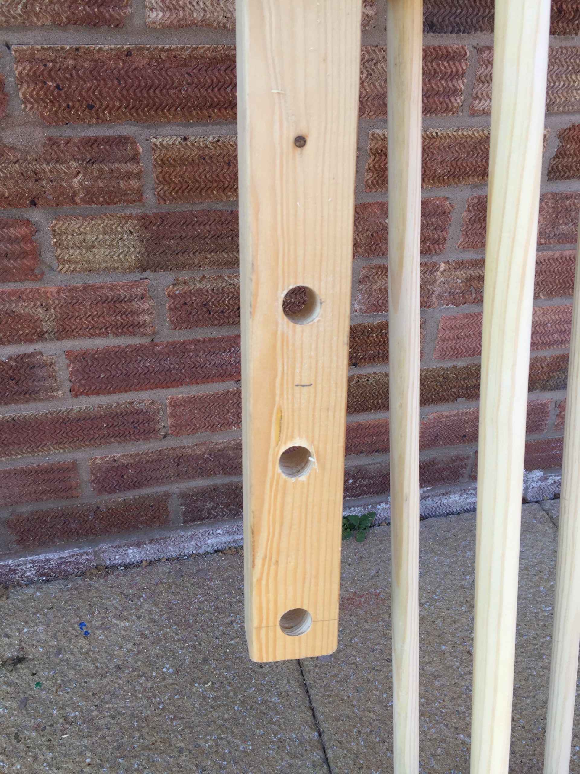
In this collection below you can see how the upper leg was really long and then I experimented by drilling holes along the length of it to try at different lengths.
Ultimately I settle on the shortest distance between hip and knee as it helped the leg hang at the right angle for the heel to touch the floor with no extra load. You can see that I covered the metal pipe with insulation to make it more comfortable and the milk bottle top washers are seen too. This central bar, I’ll call it the pelvis, was then cable tied to a backpack so I could hang it over my shoulders with the bag on the front.Extra bits of weight were added to simulate the additional load of cardboard and paper mache that were still to come.
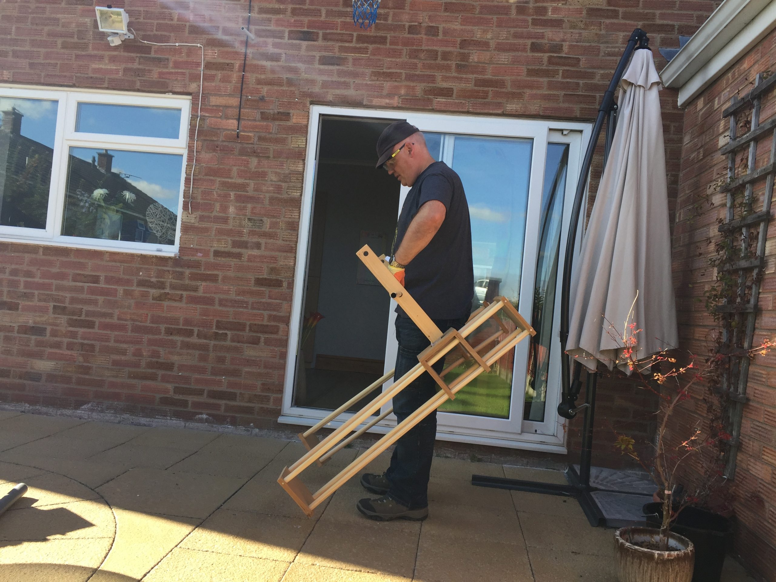
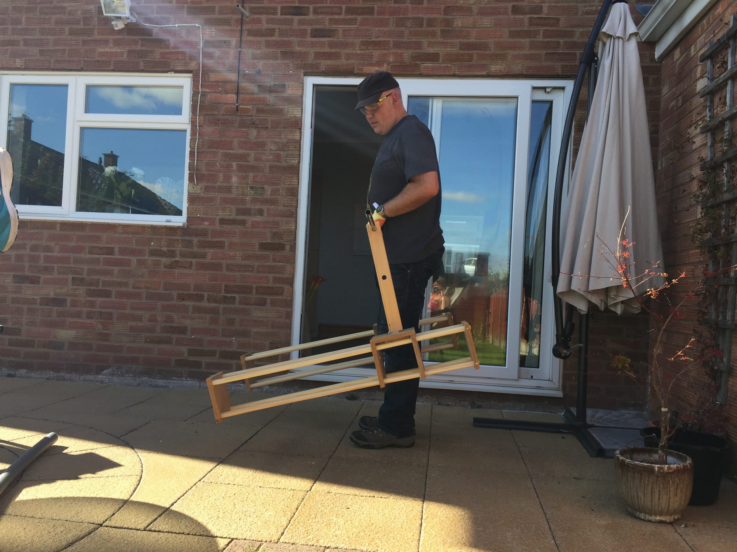
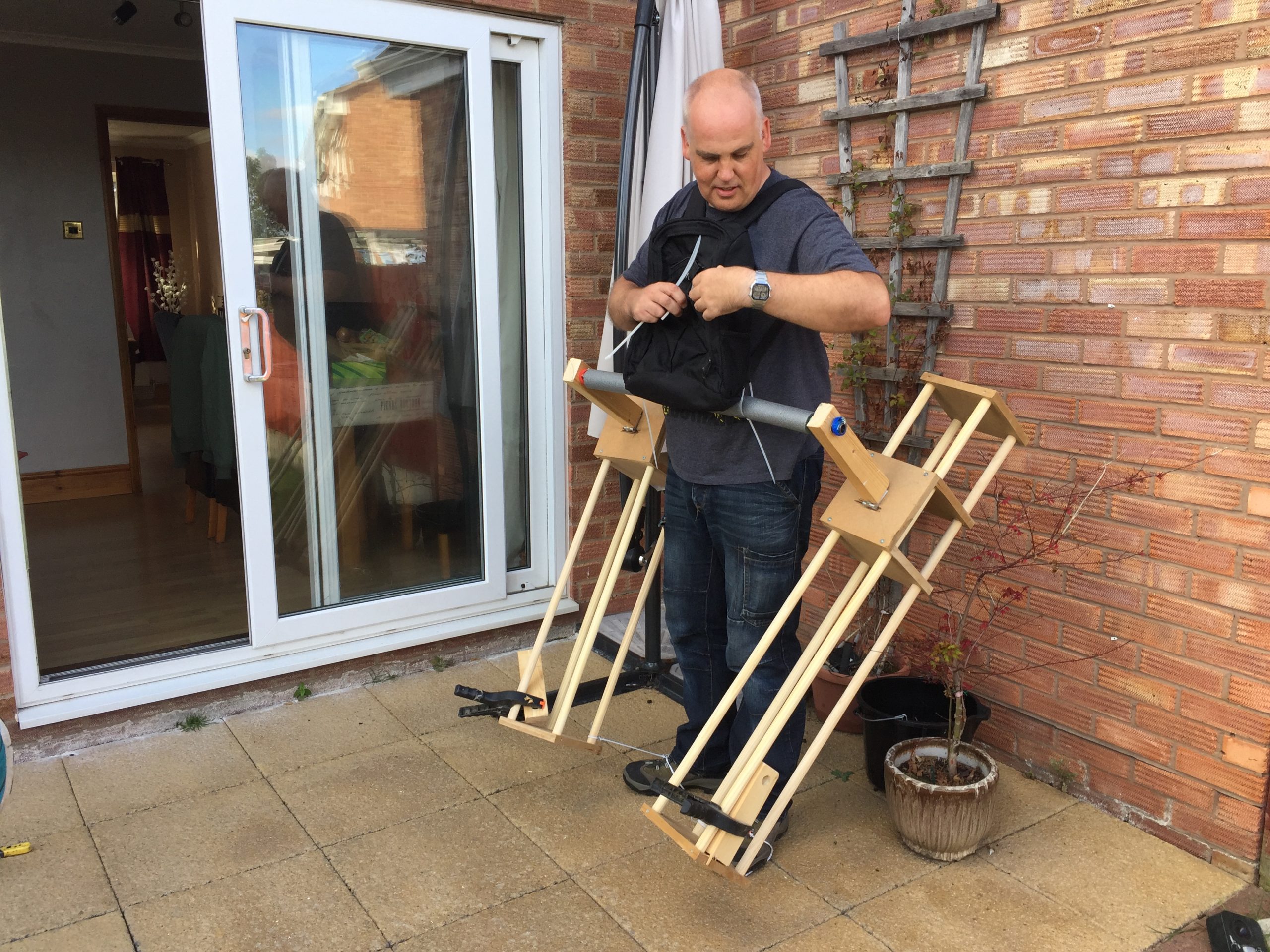
I was now happy with the concept of the legs and tied the bottom of each leg to my feet to test out the walk. Here’s a short and I mean short video of the earliest of trials.
Notes 14 and 15 show the thinking behind the frame being made from flattened conduit and the use of mdf in the side to give a strengthened piece for the gun arm to exit the body. I planned to use the conduit and flatten it using a hot air gun then pop rivet it all together for the strength.
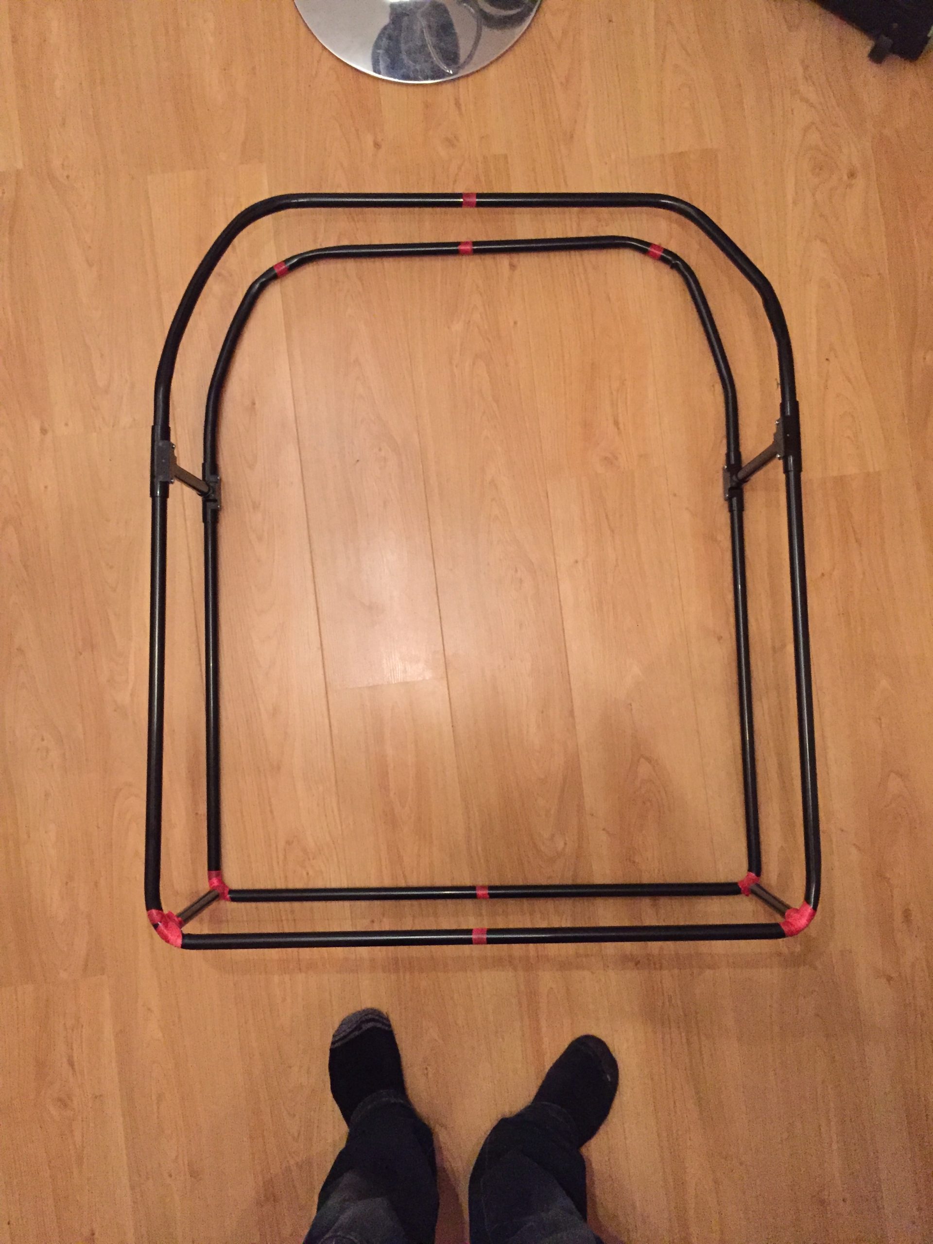
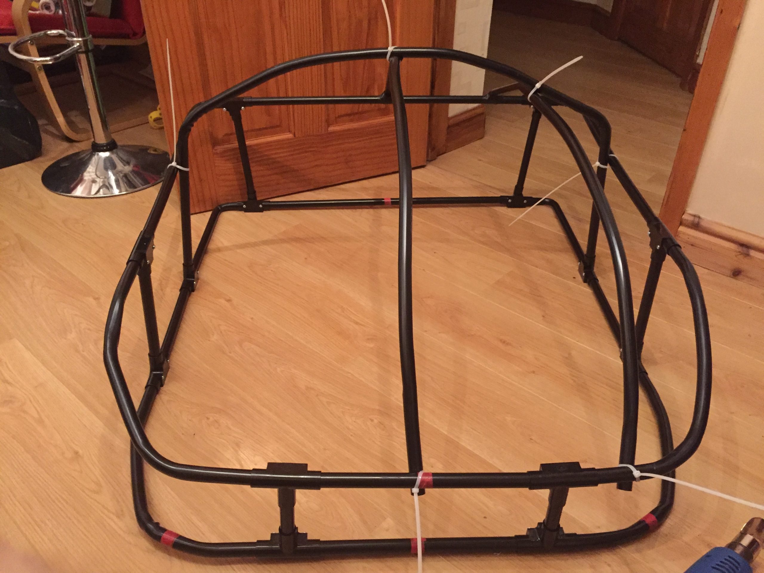
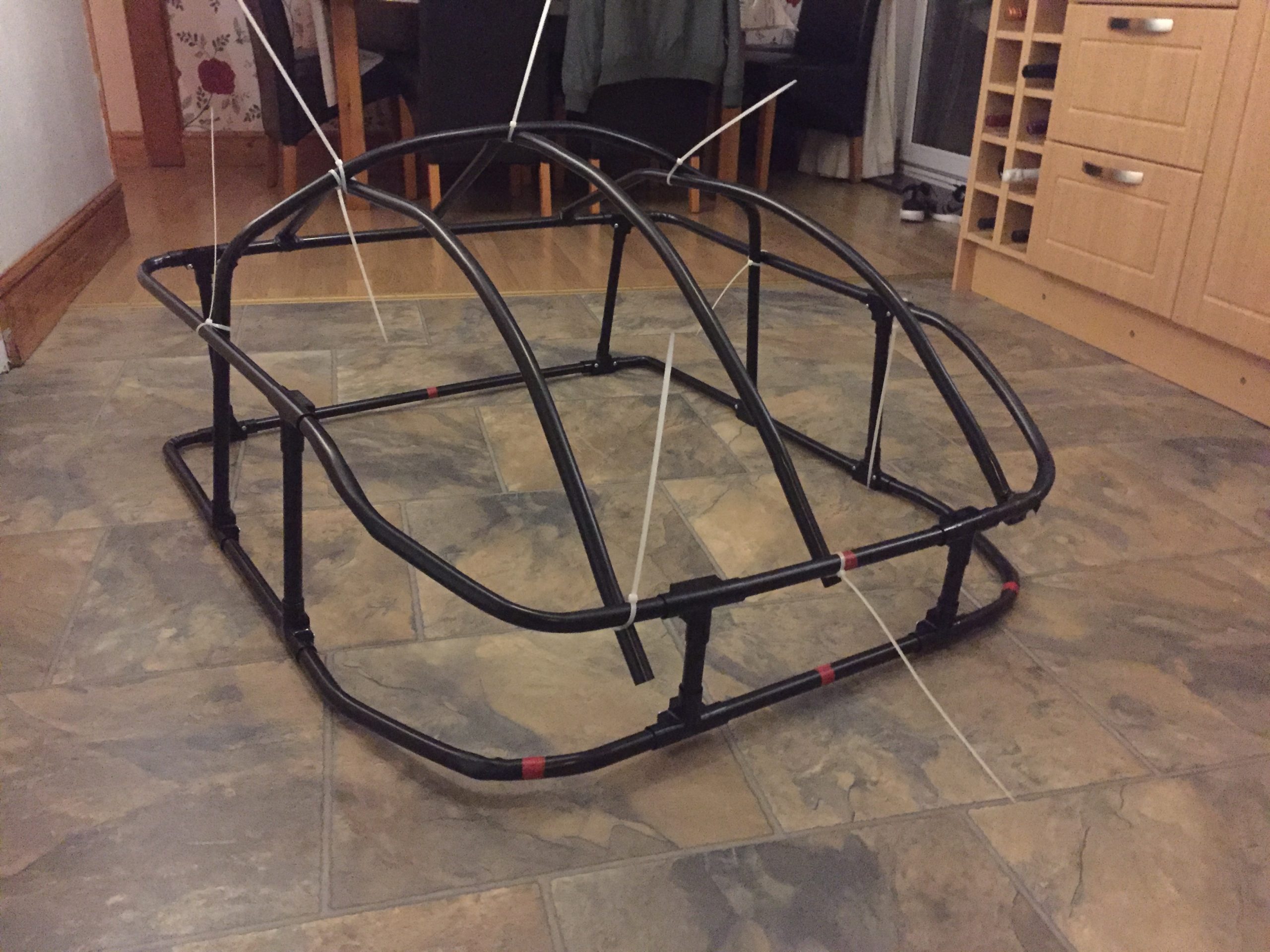
By this time I’d made the initial shape of the body to be as wide as the gait of the legs and now needed to give it some shape from front to back in the form of the black dome on the droid.
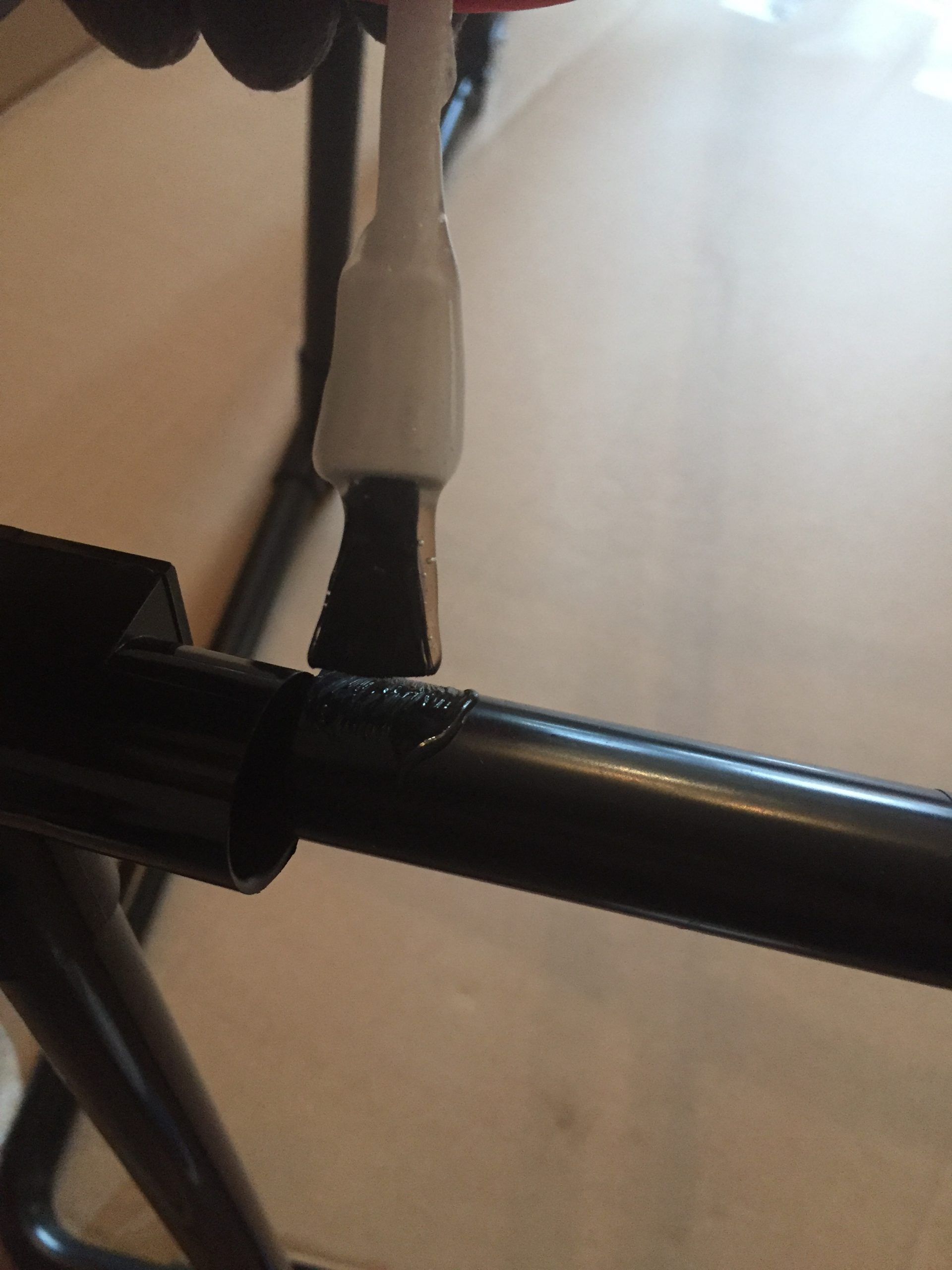
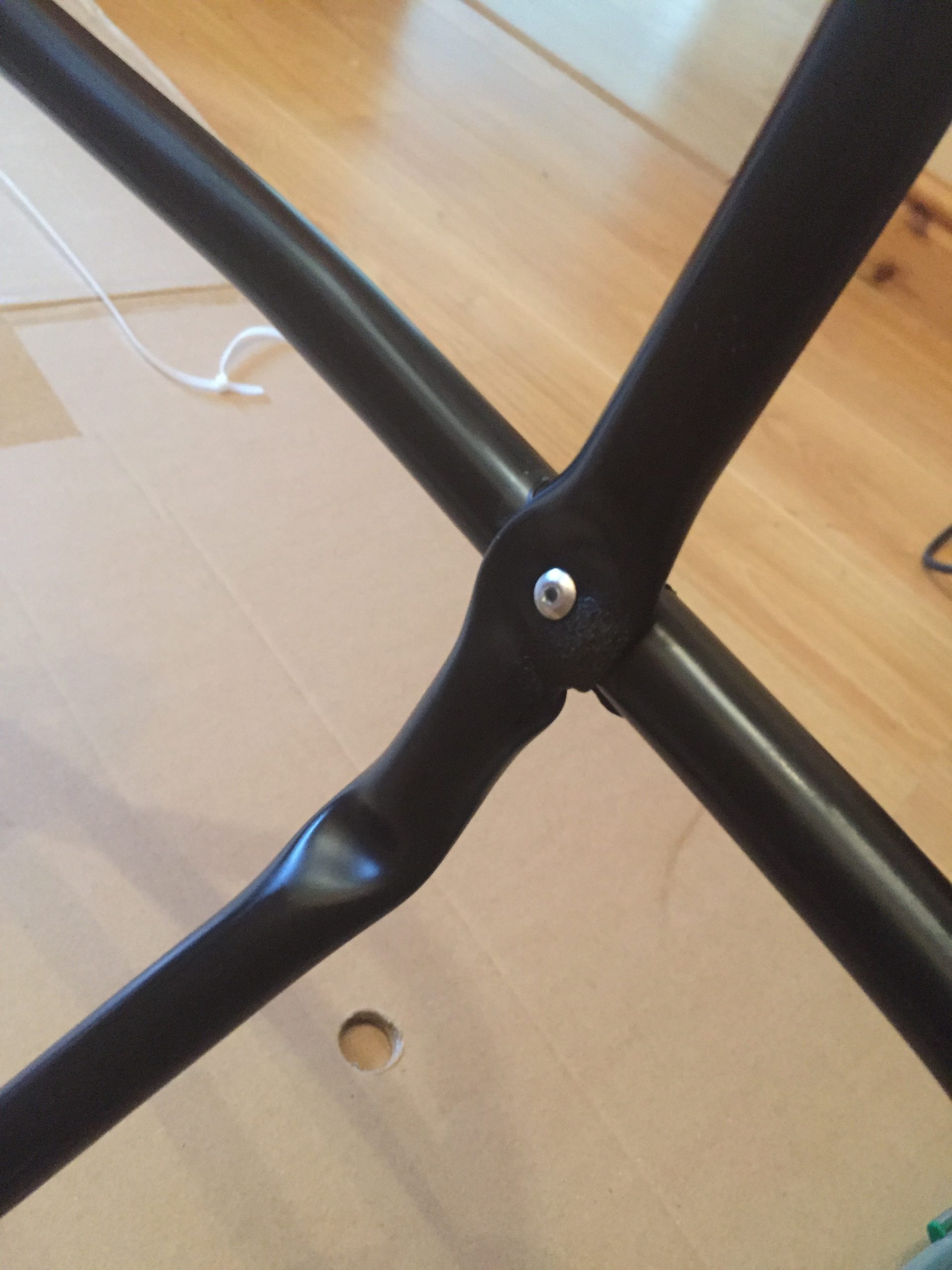
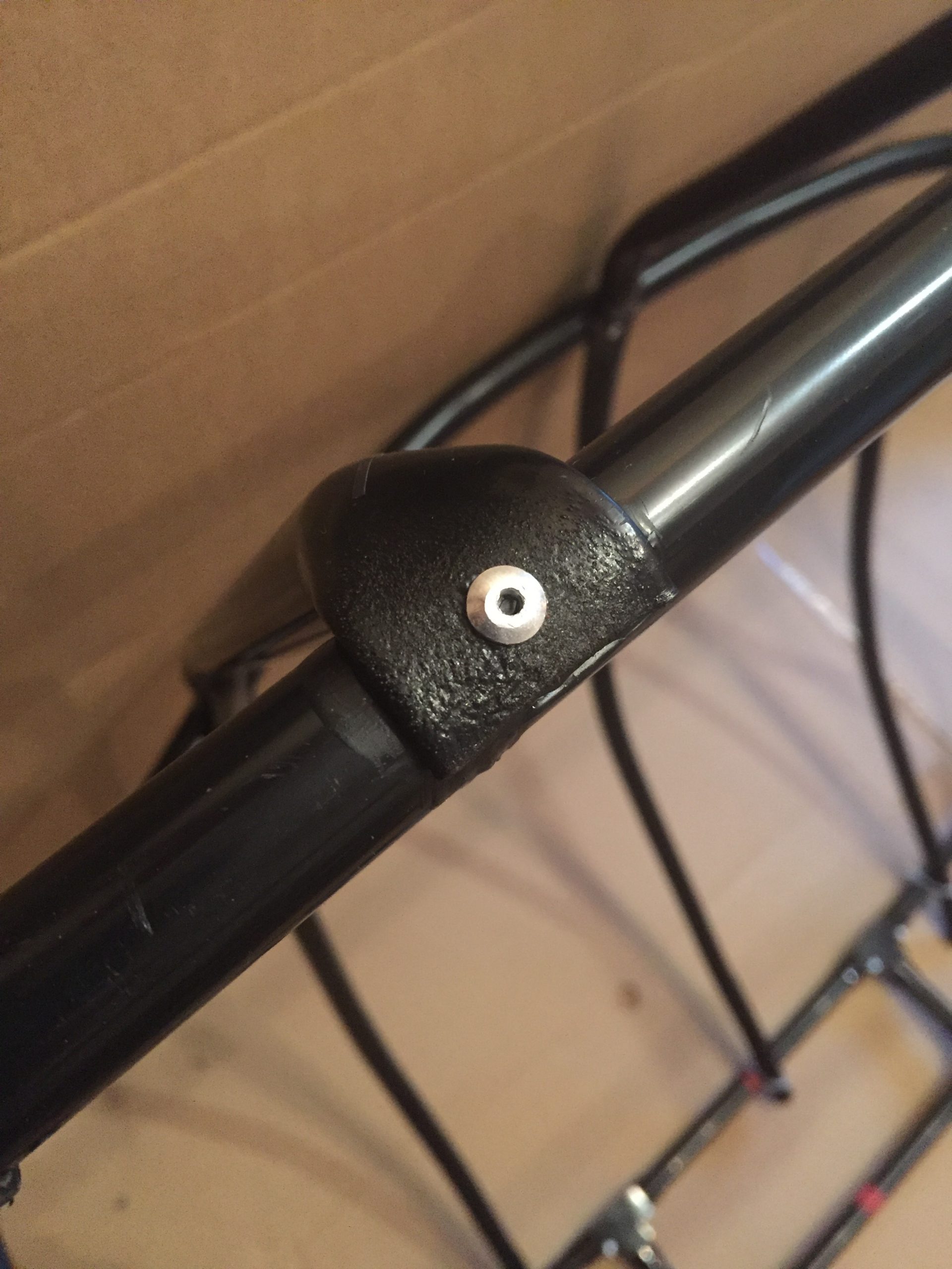
Using the black 20mm plastic conduit, some tee pieces, some inspection elbows, a bending spring and a hot air gun I was able to refine the bends and produce some three way joints. The pipes into the tees and elbows would be glued using Flo-Plast which actually melts the two surfaces together like a plastic weld. The other joints where pipes crossed would be flattened and pop riveted.
You can see in the photos below the joints I’m talking about and the final image of this set shows the structure of the body completely held together on it’s own with now cable ties or duct tape. Some of the joints were little sods to make with the bending spring and to get them similar across left and right sides was nigh on impossible. Even when I held them together to copy the shape they always ended up slightly different. The three pipes on the front (like the windscreen) were tricky too as I wanted the centre to be higher than the two outer pipes and these two to be on a path down to the sides and the front.
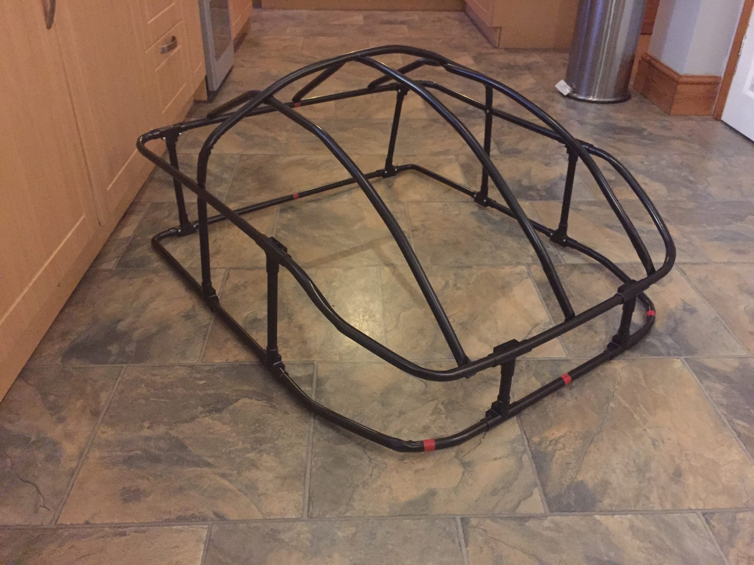
At this point I envisaged me balancing the frame on my head as it would probably be lightweight enough to do so. This was to change too as the weight of the attached goodies would make it too heavy to do this.
Whilst I was in the shed finding bits and bobs to make parts of the costume and tools to help in the quest I noticed that my long suffering wife had some left over membrane to prevent weeds growing through in the garden. Stuff like you’d put under a shingled area or decking. I figured that this would be superb to make the, what I’ll call, “screen” from. It was a black flexible mesh material that wasn’t easy to tear or damage and did let some light through. Not enough to see for moving around but enough that I wasn’t going to be in the dark all the time whilst wearing it.
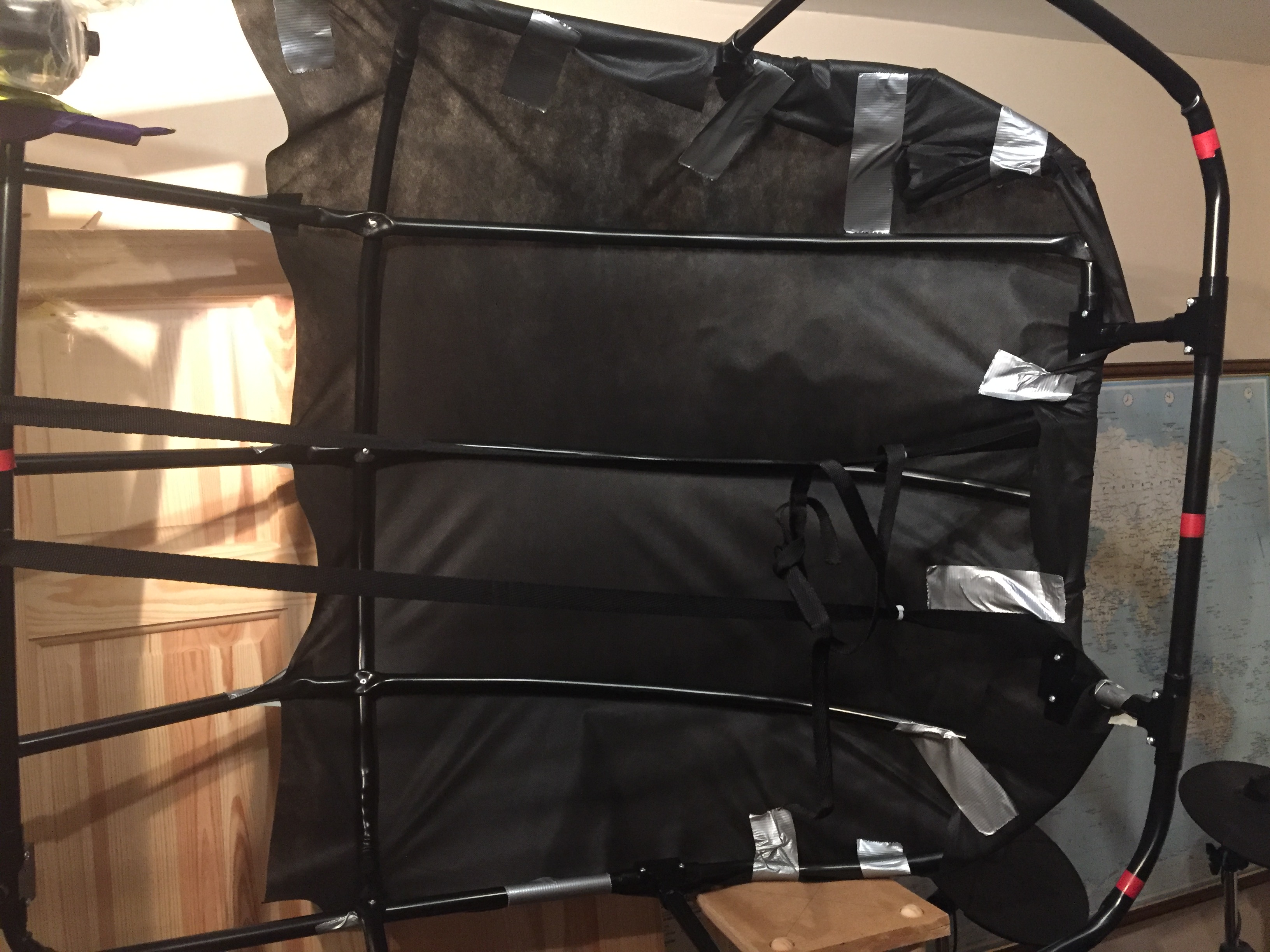
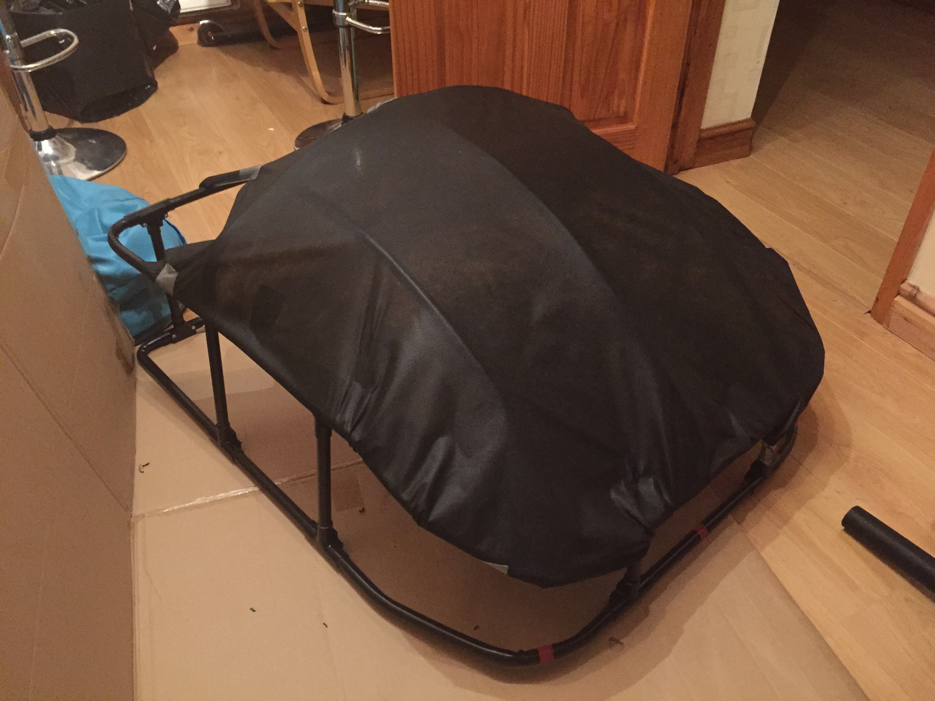
I trialled some of this over the frame using duct tape to fasten it into position and aside from a few wrinkles I thought it looked ok and decided that I’d use this in the final build.
The next step was to make the body appear solid and you’ll find the continued story in Part 3. I’ve just realised too that whilst writing this I’ve been listening to Kraftwerk’s Man Machine album.. Weird coincidence huh!?
Please feel free to comment if you have anything you’d like to say.
NOTE: Also, I link to the materials I’ve used and although I bought the parts from the places in the links, generally, I don’t endorse them or receive any payment from them in any way.
[…] ED-209 Cosplay – Part 2: Check out the Legs & Body! […]